ISY-99i/ISY-26 INSTEON:Quick Start Guide
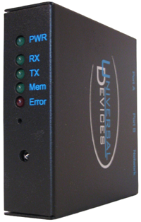
ISY-99i Series Quick Start Guide
Thank you for purchasing an ISY-99i Series device, Universal Devices, Inc. second series of intelligent, web-enabled, stand-alone INSTEON network managers/controllers. This Quick Start Guide will help you to get your ISY-99i installed and configured, and will provide links to additional resources which you may find helpful. Please read through this guide before beginning installation.
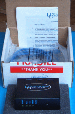
What's Included
The package should include:
- ISY-99i Series device
- (2) two standard cat5e Ethernet cables
- (1) one RS232 null-modem serial cable (PRO version only)
- Quick Start guide.
The ISY-99i Series controller also requires a Smarthome Power-Line Modem (PLM), which is sold separately.
Note: No power supply is included since ISY is powered through the PLM. If desired an external power supply can be used.
Note: The serial cable (included with the PRO version only) is a standard, DB9M-DB9F null-modem (cross-over) cable.
Requirements
- Smarthome Power-Line Modem (PLM): http://www.smarthome.com/2412s.html
- Java enabled web browser
- Router (DHCP enabled preferred), or Ethernet cross-over cable (not included) for direct connection to computer
- If using a non-DHCP-enabled router, or a direct connection to a computer which is not a DHCP server, the following are required in order to configure ISY's network parameters:
- A null-modem serial cable (included with PRO version)
- A serial port (or USB-to-serial adapter) on the computer
Installation

- Serial Connection
- Connect the DB9M end of the null-modem serial cable (included with PRO version) to ISY's Port B, and connect the DB9F end of the cable to the serial connector (or USB-to-serial adapter) on the computer.
- Network Connection
- If using a router, connect one end of an included Ethernet cable to ISY's Network jack, and connect the other end to an available port on the router. Alternately, ISY may be connected to a network switch or hub which is connected to the router.
- If using a direct connection to computer, connect one end of an Ethernet cross-over cable (not included) to ISY's Network jack, and connect the other end to the RJ-45 network connector on the computer.
- PLM Connection
- Connect one end of an included Ethernet cable to ISY's Port A, and connect the other end to the PLM.
- Note: If longer cables are required in order to reach the router or the PLM, any standard cat5/cat5e/cat6 Ethernet cable may be substituted.
- Do not use the cable that is included with the PLM.
- Apply Power
- Plug the PLM into a regular power outlet. Do not plug it into a UPS or into a protected power bar (a non-protected power bar is fine).
- An external power supply may be used with a 2412S PLM.
- An external power supply must be used with a 2413S PLM.
- 5-30 VDC
- 300 mA minimum
- Center positive 2mm male barrel jack
- A Radio Shack 273-028 set to 6V will work.
- ISY boots. The Rx, Tx, and Mem LEDs may flash briefly, and the PWR LED should be on steady. The two small green LEDs on the RJ-45 Network connector should be on, and may flash.
The serial connection is required to configure ISY's network parameters if using a non-DHCP-enabled router, or a direct connection to a non-DHCP-server computer; otherwise it is optional:
Host Computer Configuration
- Java
- Ensure that the latest edition of Java for your platform is installed on the computer. The latest Java downloads may be found at Java.com. Please note that in case you have an ISY with firmware version 3.2.6 and above, you need Java 1.7
- If you have a 64-bit version of Windows you will need to install both the 32-bit and 64-bit versions of Java.
- Please see this Java page: java_win64bit.xml
- If you have a MAC, and your ISY firmware is above 3.2.6, you MUST upgrade Java to 1.7 using Software Update. If Java 1.7 is not available in Software Update, then follow the instructions below:
- Quit all programs
- Go to Applications/Utilities and run Java Preferences. Delete all JAVA cache.
- Go here and verify your JAVA http://www.java.com/en/download/installed.jsp
- If at version 1.6 or earlier download the file it suggests. (and install if necessary)
- Reboot and then repeat step 3 until it says 1.7.
- Ensure you have the latest firmware and UI from here
- If you are using the .JNLP file, please note that Java 1.7 has a bug where the icon is not installed on the desktop. The easiest way to make the association between the Icon and the Web Start app is:
- Right-click a JNLP file in the finder and choose "Get Info" OR Choose "File>Get Info" from the Finder Menu
- In the "Get Info" window Click the disclosure triangle next to "Open With" to reveal an Applications menu
- Choose "Other..."
- Navigate to "/System/Library/CoreServices/" and choose "Java Web Start"
- Back in the "Get Info" Window Click on "Change All..." to register Java Web Start.app as the handler for the filetype.
- IP Address and URL
- Using a DHCP-enabled router or DHCP-server computer, with Internet access available:
- Start a web browser of your choice and go to http://www.universal-devices.com/99i; when prompted to authenticate, enter admin (lower case) for both user-id and password (Figure 4).

Figure 4
- In the Universal Devices Administrative Console, choose Help-->About (Figure 5A).

Figure 5A
- In the About dialog, locate My URL and write down the URL. For example, in Figure 5B, the URL is http://192.168.0.101 and the IP address is 192.168.0.101. Then close the Administrative Console (File-->Exit).

Figure 5B
- You may optionally give ISY a static IP address (see the section #Assigning ISY a Static IP Address).
- Using a DHCP-enabled router or DHCP-server computer without Internet access:
- Complete the section #Finding ISY's Current IP Address.
- If you are unable to find ISY's current IP address, complete the section #Assigning ISY a Static IP Address.
- Using a non-DHCP-enabled router or a direct connection to a non-DHCP-server computer:
- Complete the section #Assigning ISY a Static IP Address.
- Administrative Console
- Open a new web browser window and go to the URL determined in the previous step. When prompted for username and password, enter admin (lower case) for both; the My Lighting web page opens (Figure 6). This web page does not require Java and therefore may be accessed even from non-Java-enabled devices such as mobile phones. It allows viewing the status of, and controlling your devices and scenes.
- Click the Administrative Console link; the blue Administrative Console window opens. When the logon dialog appears (Figure 4), enter admin (lower case) for both username and password. This is the Java client, and requires a Java-enabled browser to access. If you would like to go directly to the Administrative Console each time you log on, without having to log on to the My Lighting web page, append the following to your URL: /admin.
- This URL may be saved (bookmark or favorite), as this is the URL through which the ISY can be accessed from any computer on the network, or from a directly connected computer.
As shipped from the factory, ISY is configured to obtain an IP address via DHCP. Since a DHCP served IP address can change whenever the lease is renewed or when ISY reboots (such as following a power failure), you may wish to give ISY a static IP address. If you are using a non-DHCP-enabled router, or a direct connection to a non-DHCP-server computer, ISY must be given a static IP address. The internal URL used to access ISY on the network will be the IP address preceded by http://.

ISY Configuration
- Time and Location
- Click on the Configuration tab and set the Time and the Physical Location for the unit (used for Sunrise/Sunset calculations). See Figure 7A.
- Enable DST if applicable to your area.
- Select Enable if the ISY is connected to the Internet and you wish to use an NTP server. The recommended minimum polling interval is 24 hours. Some NTP servers ignore requests that are frequent.
- QueryAll Program
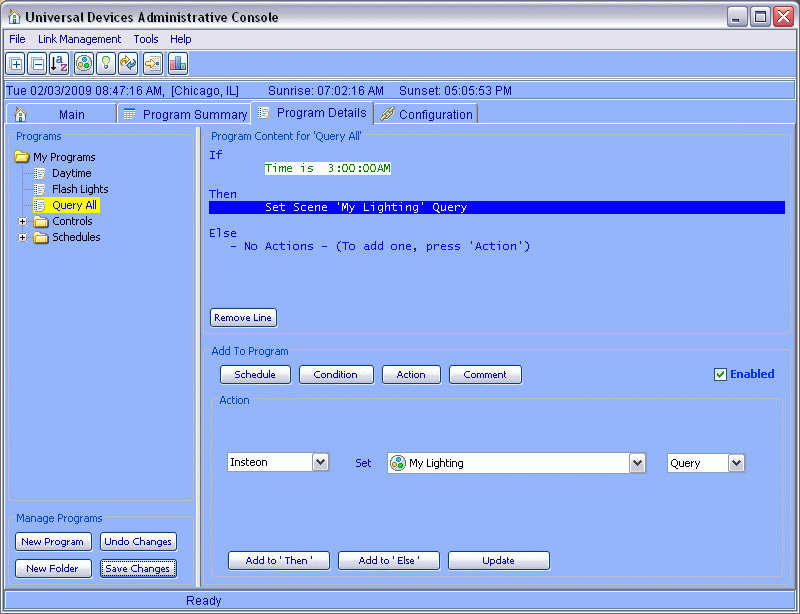
- Click on the Program Details tab and you will see a QueryAll program for the purpose of querying the unit. Please choose a time when the system is not used (e.g. 3:00 a.m.). See Figure 7B.
- Link INSTEON Devices
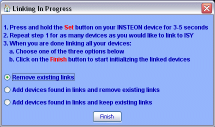
- Click on the icon and then follow the instructions on the screen. Continue linking as many devices as desired before clicking on the Finish button. See Figure 7C.
- Link Management Menu
- Register
- Don’t forget to register your unit to receive important enhancements, updates and upgrade information:
- Register

ENJOY!
For additional documentation, please visit UDI Wiki
Assigning ISY a Static IP Address
An IP (Internet Protocol) Address consists of four eight-bit bytes. Common notation has the four bytes written in decimal notation, and separated by a period. We are concerned with four network parameters (IP addresses): the device IP Address, the NetMask, the Gateway IP address, and the DNS Server IP address.
- Gateway Network Parameters
- Using a router or a DHCP-server computer:
- Determine the gateway device's IP Address. Many common routers have an IP address of 192.168.0.1 or 192.168.1.1.
- Determine the gateway device's Netmask (usually 255.255.255.0).
- Using a direct connection to a non-DHCP-server computer:
- Ensure that the computer's network parameters are properly configured. The computer's IP Address should be in the 10.0.0.0/8 network, the 172.16.0.0/12 network, or the 192.168.0.0/16 network. The NetMask should usually be 255.255.255.0. The Gateway and DNS Server IP addresses should be the same as the computer's IP Address. For example:
- IP Address = 192.168.1.1
- NetMask = 255.255.255.0
- Gateway = 192.168.1.1
- DNS Server = 192.168.1.1
- Ensure that the computer's network parameters are properly configured. The computer's IP Address should be in the 10.0.0.0/8 network, the 172.16.0.0/12 network, or the 192.168.0.0/16 network. The NetMask should usually be 255.255.255.0. The Gateway and DNS Server IP addresses should be the same as the computer's IP Address. For example:
- ISY Network Parameters
- Prepare the network parameters to be assigned to ISY. ISY's IP Address should be the same as the gateway device's IP Address in the first three segments, and different from the gateway device's IP Address in the last segment only. The NetMask should be the same as the NetMask of the gateway device. The Gateway and DNS Server should be set to the IP Address of the gateway device. For example:
- IP Address = 192.168.1.101
- NetMask = 255.255.255.0
- Gateway = 192.168.1.1
- DNS Server = 192.168.1.1
- ISY Shell
- Connect and log in to the ISY Shell (see the section #Connecting to the ISY Shell).
- Type the CT command (upper case) followed by <ENTER>. When prompted, enter the values previously prepared for IP Address, NetMask, Gateway and DNS Server, following each with <ENTER>. When prompted with Save Changes, enter Y (upper case). ISY will reboot.
- Start a web browser of your choice and go to the URL (IP address) assigned to ISY, for example: http://192.168.1.101; when prompted to authenticate, enter admin (lower case) for both user-id and password (Figure 4 above). This URL may be saved (bookmark or favorite), as this is the URL through which the ISY may be accessed from any computer on the network, or from a directly connected computer.
- If desired, the serial cable may now be disconnected from ISY and from the computer.
The Gateway Device is the router or computer to which ISY is connected.
Connecting to the ISY Shell
Connecting to the ISY Shell Using Telnet
Note: In order to telnet to ISY, ISY's current IP address must be known.
- Determine ISY's current IP address (see the section #Finding ISY's Current IP Address).
- If using the Windows telnet command (Note: The Windows telnet command is installed by default on Windows XP, but not on Vista. On Vista, you will need to install the telnet command from Windows Components.):
- If using another telnet client, connect to ISY's current IP address.
- When prompted for Username: enter admin (lower case) followed by <ENTER> (Figure 8B). When prompted for Password: enter admin (lower case) followed by <ENTER>. The ISY Shell is displayed (Figure 8C). All input to the ISY shell must be in UPPER CASE.

Figure 8B 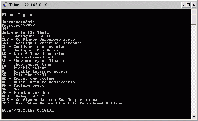
Figure 8C
Connecting to the ISY Shell Using the Serial Port
- Connect one end of a serial null-modem cable (included with PRO version) to ISY's Port B, and connect the other end to the serial connector (or USB-to-serial adapter) on the computer.
- Start a terminal program (such as Windows HyperTerminal) and configure for 115200bps, 8N1, Xon/Xoff, and for the appropriate COM port.
- Type a few characters until prompted for Username: and enter admin (lower case) followed by <ENTER>. When prompted for Password: enter admin (lower case) followed by <ENTER> (Figure 9A). The ISY Shell is displayed (Figure 9B). All input to the ISY shell must be in UPPER CASE.

Figure 9A 
Figure 9B
Note: For more information on connecting to and using the ISY Shell, consult the Advanced Configuration Guide.
Finding ISY's Current IP Address
Finding ISY's Current IP Address from the Administrative Console
- In the Universal Devices Administrative Console, choose Help-->About (Figure 5A).
- In the About dialog, locate the My URL line; the URL contains ISY's current IP address. For example, in Figure 5B, the URL is http://192.168.0.101, and the IP address is 192.168.0.101.
Finding ISY's Current IP Address from the Router
- Log on to your router. [See your router manual for instructions. Many common routers may be accessed at an address of 192.168.0.1 or 192.168.1.1 .]
- Locate your router's DHCP Client Table. Your router may use a different name, but it should have a table which lists the devices currently connected to the router.
- Within the table, locate ISY:
- If the table contains a Name or Description column (some routers), locate the line on which that column contains the word ISY (and other text).
- If the table contains a MAC Address or Physical Address column (some routers), locate the line on which that column contains ISY's MAC address (see the section #Finding ISY's MAC Address).
- From the table line identified in the previous step, obtain ISY's IP address.
Finding ISY's Current IP Address from a Windows Command Console
- Open a Command Console (DOS Prompt) Window:
- Go to the Start menu and choose Run.
- In the Run dialog, enter cmd and click OK.
- At the command prompt, type the command:
- arp -a <ENTER>
- The arp command will display a table containing the IP Address and Physical Address of each of the network-connected devices it discovers.
- Locate the line on which the Physical Address column contains ISY's MAC address (see the section #Finding ISY's MAC Address).
- From the table line identified in the previous step, obtain ISY's IP address (Figure 10).

Figure 10
Finding ISY's MAC Address
- A MAC Address is a six-segment string, in which the segments are separated by a colon (':'), and each segment contains two hex digits (a hex digit is one of the numeric digits '0' to '9', or one of the alphabetic characters from 'a' to 'f'); for example: 00:03:2a:19:f4:cd.
- If you are currently able to connect to ISY, either:
- Open the Universal Devices Administrative Console:
- Open a new web browser window:
- In the web browser, go to http://your.isy.ip.address/desc .
- In the displayed page, locate the line which begins with <UDN> and ends with </UDN>; this line contains the identifier uuid: followed by the MAC address.
- If you are not currently able to connect to ISY, the following may help to identify ISY's MAC address within a router table or an arp table:
- In general, the ISY's MAC address will begin with one of the following segment groups:
- Early ISY's will have a MAC address which begins with the segments 00:03; these MAC addresses are from NetBurner.
- Newer ISY's will have a MAC address which begins with the segments 00:21:B9, which is the Universal Devices, Inc. ID.
- In general, the ISY's MAC address will begin with one of the following segment groups:
Status Display of ISY's LEDs
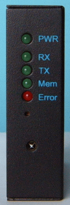
The state of ISY's LEDs convey a certain amount of status information, as follows:
- Front Panel LEDs:
- PWR: should be on steady; if it is off, ISY does not have power.
- Rx, Tx and MEM OFF: ISY is idle.
- Rx Blinking: ISY is receiving INSTEON traffic.
- Rx ON Steady: ISY cannot communicate with the PLM; either the PLM or the cable are defective.
- Tx Blinking: ISY is transmitting INSTEON traffic.
- MEM Blinking: ISY is accessing memory.
- ERR Blinking: File system error. Please phone our Support Center: 818.631.0333
- MEM and ERR Blinking: ISY cannot communicate with attached router (or computer, if directly connected). Cable bad, or misconfiguration in ISY or in router (or computer, if directly connected).
- Note that, once programmed, the ISY does not have to be connected to function.
- Rear Panel LEDs:
- The RJ-45 Network jack includes two small green LEDs, which should both be on, and one of which will blink when network traffic is present. If they are not on, ISY cannot communicate with router (or computer, if directly connected); see MEM and ERR Blinking above (Figure 3 above).
Resources
The following resources provide downloads, documentation, and information which may be of interest and assistance to ISY users:
- The Universal Devices, Inc. Resources page provides links to download:
- The latest tested Java edition
- The Universal Devices Wiki provides:
- All the latest ISY documentation
- How-To Guide
- Tips, Techniques, and FAQs
- Reviews.
- The Universal Devices Forum provides:
- A place to ask questions and discuss ISY and other UDI products, including
- Usage examples
- Program examples
- Feature requests
- Beta firmware.
- A place to ask questions and discuss ISY and other UDI products, including
- User Guide in PDF format.
- iPhone and iLinc Pro New User Walkthrough YouTube video that can apply to any new user.
- Smarthome PLM (Power-Line Modem), part number 2412S (discontinued).
- PowerLinc Modem - INSTEON Serial Interface (Dual-Band), part number 2413S (required by ISY).
Related Pages

