ISY-99i/ISY-26 INSTEON:Working With Scenes - in-depth tutorial
INSTEON Devices and Local Settings
Every INSTEON device managed by ISY is listed under My Lighting in the tree view (the left pane) of the Main tab. Selecting My Lighting in the tree view will display in the right pane, a list of all INSTEON devices managed by ISY, along with their current status.
Selecting a device under My Lighting will display its current status and its local settings in the right pane. A relay device, such as a SwitchLinc Relay or an Icon On/Off switch, will have only two possible states: On or Off. A dimmer device will have an on-level which may vary between zero and 100 percent, and a ramp-rate which may vary between .1 seconds and 9 minutes. The on-level and ramp-rate may be adjusted by use of the sliders in the right pane.
These local settings are the settings which will be used by the device when it is manually switched On or Off at the switch itself, or when it receives an ON or OFF command from ISY either in response to clicking the On or Off buttons in the right pane when the device is selected in the tree view, or when an ISY program sends an ON or OFF command to the device. When a FAST ON or FAST OFF command is received, the device will turn full on or full off, respectively, at the fastest possible rate.
In order for these local settings to take effect after being modified, the device must be rebooted by disconnecting its power for a few seconds. This may be done by pulling the air-gap button, by unplugging the device, or by turning off the circuit breaker at the service panel. When power is restored to the device, the new local settings will take effect. The KeypadLinc is the sole exception; its local settings will take effect without being rebooted.

What Is A Group?
In INSTEON terminology, a group is a unidirectional link between a single controller device, and one or more responder devices. All INSTEON devices employ bidirectional communication, and all are theoretically capable of acting as either a controller or a responder. In practice, a few types of devices (InlineLincs, most plug-in modules such as LampLincs and ApplianceLincs) do not act as controllers since they either have no local control, or do not send notifications when controlled locally. Similarly, a few devices such as ControLincs and RemoteLincs, do not act as responders, but only as controllers. Finally, some devices (SignaLinc, Access Point) are neither controllers nor responders, and do not participate in groups.
Many devices such as Icon, SwitchLinc, and ToggleLinc dimmers and relays, are able to act as a controller of only one group. KeypadLincs may be controllers of as many as five or eight groups, depending on whether configured for six-button or eight-button operation [in six-button mode, the top and bottom buttons act as On and Off buttons respectively for the local load, while the remaining four buttons toggle between On and Off]. ControLincs may be controllers of up to five groups, and RemoteLincs controllers of up to six groups. In general, a device may be controller of a number of groups equal to its number of buttons/paddles. Finally, the PLM may be a controller of up to 255 groups.
All responder devices may be responders in multiple groups. Responder devices may be added to, and removed from an established group. Each responder device maintains its own on-level and ramp-rate settings for every group in which it participates. When a device receives an ON command for a group in which it is a responder, it changes to its predefined on-level at its predefined ramp-rate. When it receives a FAST ON command, it ignores those settings and turns full on at the fastest possible rate. It may also respond to other commands sent to the group, including OFF, FAST OFF, BRIGHTEN and DIM. An OFF command will use the preset ramp-rate, while a FAST OFF will turn the device off at the fastest possible rate.
The controller of a group is usually also a responder of the group. For a single-button controller such as a SwitchLinc, or for the primary button(s) of a KeypadLinc, it is a responder by default, since operating the paddle/button(s) simultaneously operates the local load as well as any group of which it is the controller. In this case, the local load operates according to the local settings. However in the case of a KeypadLinc secondary button, the KeypadLinc's local load is not a responder of a group programmed on that button unless it is specifically included in the group.

What Is A Scene?
Scenes are closely related to groups. In ISY terminology, a scene is a named collection of devices, and is displayed in the tree view of the Main tab. When a scene is created by the user, it will initially be empty. The user may add and remove devices from a scene at any time.
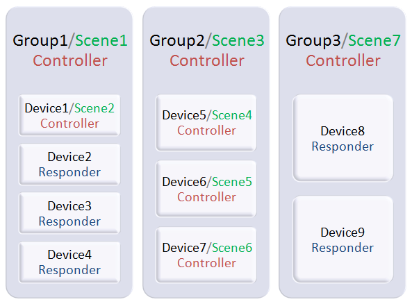
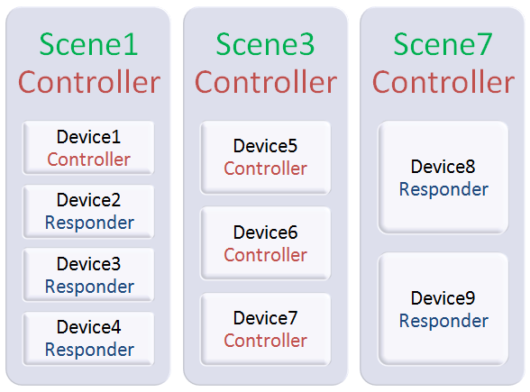
An ISY scene is a super-set of an INSTEON group. Like a group, a scene may contain multiple responder devices, but unlike a group, a scene may also contain multiple controller devices. To be useful, a scene must have at least one controller device, and at least one responder device. The ISY/PLM is considered a controller of every scene managed by ISY, so a scene may be useful even without additional controllers.
Because an INSTEON device maintains separate on-level and ramp-rate settings for each group to which it responds, it follows that in a scene with more than one controller, the on-level and ramp-rate settings of the responders may be set separately for each controller.
When a scene contains more than one controller, ISY automatically creates the required cross-links so that each of the controllers' status indications, such as a SwitchLinc's level-indicating LEDs or a KeypadLinc's button LED, will be updated when the scene is controlled from any other controller in the scene. In this sense, an ISY scene is a multi-directional group. If a scene were created manually without ISY, all of the required unidirectional INSTEON group links and cross-links would need to be manually created.
It should be noted that all links created by ISY are standard INSTEON links, and are stored in the INSTEON devices. Therefore, after the required scenes are created, the ISY/PLM could be removed from the network, and the scenes would continue to function as programmed.
Working With Scenes
Selecting a scene in the Main tab's tree view will display in the top portion of the right pane, a list of all devices which are responders in that scene together with their current status, similar to the list of all managed device displayed when My Lighting is selected. The bottom portion of the right pane will display the ISY scene settings on-level and ramp-rate sliders for each of the scene's responder devices. These are the settings which will be used when the scene is controlled by ISY, either in response to user actions in the GUI, or in response to ISY programs or schedules.
When the scene is expanded in the tree view, it opens a list of all devices in the scene, with controllers displayed in red typeface, and responders in blue typeface. Selecting a controller within a scene displays in the right pane a list of the scene's responder devices with status on top, and a list of their on-level and ramp-rate settings on the bottom, similar to that displayed when the scene is selected. But in this case, the settings displayed are the controller-specific scene settings which will take effect when that particular controller is used to control the scene. When these settings are changed, the changes take effect immediately.
Selecting a responder device within a scene displays in the right pane the device's status and local settings, and is the same display as shown when the device is selected in My Lighting. Changing these settings in either location will have the identical effect.
For the steps below, a few screen-shots may be found at Create a Scene.
Adding a New Scene
To add a new scene, open the Link Managment menu and choose New Scene. A New Scene window will be displayed, allowing the new scene to be given a name.
Removing a Scene
In the tree view of the Main tab, right-click on the scene and from the context menu choose Remove Scene. A Confirm window is displayed, and if OK is chosen the scene is removed.
Adding Devices to a Scene
Devices may be added to a scene one at a time, or an entire group of devices may be added at once. To add a device or group of devices to a scene:
- Select the devices to be added:
- In the tree view of the Main tab, click on the device to be added, or hold down the <Control> key and click one at a time on a group of devices to be added and then release the <Control> key. You may click on device names anywhere they appear within the tree, such as under My Lighting or under other scenes. To select a contiguous group of devices, click on the first device of the group, press and hold the <Shift> key, click on the last device of the group, and release the <Shift> key. In this case, the devices must all be within the same branch of the tree, such as My Lighting or another scene.
- Add the devices to the scene in either of the following ways:
- Drag the selected devices onto the scene name in the tree, or
- Right-click and from the context menu choose Add to Scene .... A Choose Scene window will open, allowing you to select the desired scene.
- Set the devices as controllers or responders:
- A Confirm Add window will open, listing the devices to be added to the scene. For each device in the list, select the device and choose whether it should be added to the scene as a controller or a responder. The default is responder for all devices except those which are controller-only devices. When all devices are correctly set, click the OK button and the devices will be added to the scene.
- Note: If none of the devices being added are capable of acting as both controller and responder (each device being added is either a responder-only or a controller-only device), then clicking the OK button will not be required; the devices will be added automatically.
Removing a Device from a Scene
In the tree view of the Main tab, right-click on the device within the scene, and from the context menu choose Remove from Scene. The device is removed from the scene immediately; no confirmation window is displayed.
"Scenes" and "Groups" (Forum Thread)
Groups Versus Scenes (Forum Thread)
Scenes 101 for a Nooblinc (Forum Thread)