ISY-99i/ISY-26 INSTEON:Link Management Menu
Just as you manually link a pair or multiple INSTEON devices to allow them to communicate with each other, the ISY needs to be linked with all the INSTEON devices it needs to manage or communicate. This menu allows you to link the ISY to all or selected INSTEON devices.
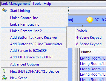
Please see Figure 7 for all Link Management menu options.
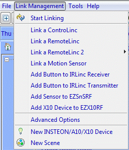
Common Options
Remove Existing Links
This will clear all the existing links in the device. It is useful on new or used devices to ensure that no stray links are left in the device.
Add devices found in links and remove existing links
This option will automatically add all the other devices linked to this device and then delete the links from the device. You can then use the ISY to create all new scenes with no fear of ghost links remaining.
Note: This option does not generate the links between devices nor does it regenerate the scene/group memberships. It simply finds and links devices found.
Add Devices Found in Links and keep existing links
This option is the same as “Add Devices Found in Links” except it does not overwrite the device settings, manual or otherwise. It will bring all the links found in each discovered device, try to make scenes out of the relationships, and maintain a copy of all the settings the device already contains.
Depending on the number of devices linked and the type of devices, ISY’s reprogramming of the devices may take roughly 10 seconds to 1 minute per device. Please be patient while ISY reprograms the devices and do not perform any operations on your INSTEON devices.
WARNING This procedure assumes that your previous tools have created correct links between devices and there are not half links, dead devices, and other aberrations. In short, if you are certain your previous tools (including manual) have created ALL the links properly (no half links, no dead devices still in links, all databases are clean and defragmented), this method will cut your migration to just a few button clicks and renaming the discovered nodes. On the other hand, if you are not sure this procedure might actually cause you to spend more time just to find the root cause of many unexplained anomalies.
Start Linking
The basic method of linking an INSTEON device is to set a device as a controller in linking mode then going to the responder and set it to linking mode. The same method is true in linking the ISY to the devices. You set the ISY (the controller) to linking mode then go each responder and set those to linking mode.
Select this menu to start linking all devices, except the ControLinc, RemoteLinc and MotionSensor, to the ISY. The linking process allows the ISY to build a database of devices in the network and the relationships between each or multiple devices, and to program these devices.
When you set the ISY in linking mode, this sets it to multilink mode. In multilink mode, the controller is able to read or link with one device set in link mode, one after another. So as long as Linking in Progress dialog is open, the ISY will be in multilink mode.
If you do not see Linking In Progress dialog, then check trouble shooting section: Tools_Menu|PLM_Info/Status. If the RX light on the ISY is solid on the PLM or the cable to the PLM is bad.
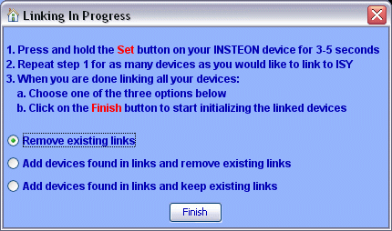
To link devices:
- Choose this menu option
- Select the link option.
- When the “Linking In Progress” (see Figure 8) dialog appears, press the “Set” button on each new INSTEON device (light, switch etc.) for as many devices as you desire.
- When you are done linking all the desired INSTEON devices, click on the “Finish” button on the Linking in Progress dialog.
This operation performs the same action as the Start Linking button on the tool bar (). When a linking session is in progress, the icon for this button changes to (
). The new device(s) should automatically show up on the ISY GUI when they are linked.
Link a ControLinc
Choose this menu to link a ControlLinc.
- The Insteon address is on the back of the ControLinc, usually under the table-top stand.
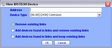
Enter the Insteon address in the requester. Then click on the “Ok” button (see Figure 9).
Note: You cannot discover or find other devices linked to the ControLinc using this option.
Link a RemoteLinc
Choose this menu item to link a RemoteLinc.
- The Insteon address is on a sticker inside the battery compartment.
When the “Link a RemoteLinc” dialog appears, press and hold the “Bright" and "Dim” buttons for 10 seconds or until the RemoteLinc’s light starts flashing. Then click on the “Ok” button (see Figure 10).
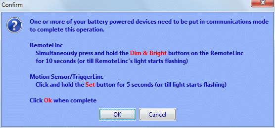
Enter the Insteon address of the RemoteLinc and press okay.
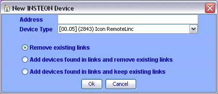
When done linking communication mode can be quit by pressing the All Off button.
- Buttons can be added to scenes the same as any other controller.
RemoteLinc FAQs
If one of the numeric buttons is pressed to exit linking mode that button will no longer send the On and/or Off commands.
A simple factory reset (without removing the RemoteLinc from the ISY) followed by a Restore - ensuring that you press the All Off button to exit linking mode
A full recovery procedure would be to:
- Remove the RemoteLinc from the ISY.
- Factory reset the RemoteLinc.
- Re-link the RemoteLinc to the ISY - ensuring that you press the All Off button to exit linking mode when done.
- Re-establish your button scenes.
Link a RemoteLinc2
3.1.17+
Choose this menu item to link a RemoteLinc2. Select the proper device from the sub-menu; Switch, 4-Scene Keypad, or 8-Scene Keypad.
- Put RemoteLinc2 in Programming Mode:
- Ensure the on/off switch is in the On position
- Press and hold the Set Button at the base of the RemoteLinc2 until the LED starts flashing green (takes about 3 seconds)
- The Insteon address is on a sticker on the back of the RemoteLinc2.
After the nodes are added to the ISY press the set button on the RL2 twice to quit linking mode.
- To maintain compatibility with the 4-Scene Keypad an 8-Scene Keypad uses groups 1, 3, 5, 7 for the buttons on the right side of the RemoteLinc2 (B, D, F, H) and groups 2, 4, 6, 8 for buttons on the left of the RemoteLinc2 (A, C, E, G).
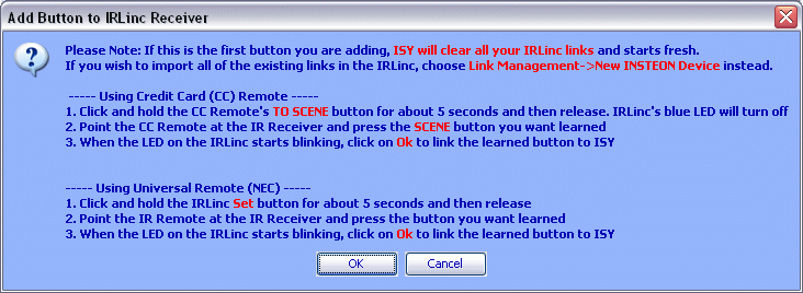
Add Button to IRLinc Receiver
Note: The Scene Control buttons (A-H) are On/Bright, Off/Dim buttons and control only one scene. Once either the On or Off button is linked to the ISY the other button is automatically linked.
Create Non-Toggle Links - (Always sends only on/off commands)
This can be handy if you want to create a button that is “All Off” or “Movie Time” (or other situations where you want the button to do the same thing every time you press it). This is also sometimes referred to as “non-toggle” mode.
- Select the "Add Button to IRLinc Receiver in the ISY Link Management pulldown menu
- Press & hold the IRLinc Set button for about 5 seconds, then release
- Blue LED will turn Off
- Point your IR remote at IR Receiver, and press the button to be learned
- Blue LED will begin blinking
- Tap IRLinc’s Set button once (to always send an on), or twice (to always send an off)
- Blue LED will continue blinking
- On the ISY, click on Ok to link the learned button to ISY
- Blue LED will return to on as normal after ISY completes linking
Optional: Factory Resetting your IRLinc
If you remove all the links to the IRLinc from the ISY it should clean up everything, but just in case you need to you can factory reset the IRLinc before linking it to the ISY.
- Unlink all the links in you ISY to the IRLinc
- Unplug the IRLinc, wait 10 seconds
- Press and continue to hold the Set button for 5 seconds while plugging the unit back in, then release
- About 20 seconds after releasing the Set button, blue LED will flash twice to indicate a successful reset
- Note: Blue LED may or may not be on during reset
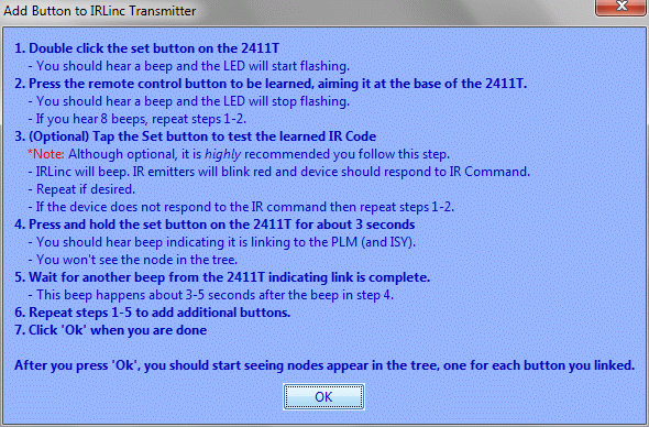
Add Button to IRLinc Transmitter
Add Sensor to EZSnSRF
EZSnsRF Wireless Sensor Receiver Quick-Start Guide
Add X10 Device to EZX10RF
Step 8 should read:
8. Click and hold the EZX10RF Set button for 4 seconds to finish the process. The led should return to a steady dim glow.
EZX10RF Wireless Sensor Receiver Quick-Start Guide
Advanced Options
Only available in firmware version 2.6.13+
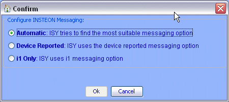
Smarthome has introduced a new protocol which uses extended messaging called i2. This is intended to make communication faster and more reliable. Some devices introduced during the changeover have both protocols enabled and can sometimes report as i2 although the protocol is not fully implemented. Universal Devices has added, for firmware version 2.6.13, an option to select the original Insteon communication protocol, termed i1, in case the Automatic option fails.
- This option should normally be left on Automatic which uses a query into the device database to determine the best way of communicating.
New INSTEON Device
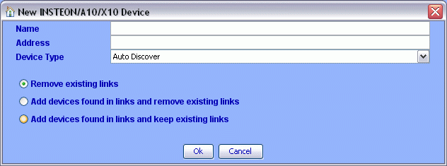
Choose this menu if you already know the INSTEON address of a device and if you do not wish to use the regular linking method of pressing the “Set” button.
After selecting this menu option, the “New Insteon Device” dialog appears as shown in Figure 11:
- Enter the INSTEON address of the device using the following format where A, B, and C are the address parts as depicted on the INSTEON device itself
- A B C or
- A.B.C
- Optionally you can select the Device Type from the drop down list
- Click on “Ok"
This operation performs the same action as the New INSTEON Device button on the tool bar ().
Link a KeypadLinc
Link a Motion Sensor
Link an I/OLinc
Link a Garage Door Control & Status Kit
Linking a Garage Door Control & Status Kit
Link an IRLinc Transmitter
Link a Thermostat
Link a TriggerLinc
Link an Leak Sensor
New Scene
Creating Scenes in ISY allows the user to set ramp rates, set on level, link or group devices without physically going to each device(s) to manually set, link or group them. Let’s say you want to link a device in a bedroom to a device in the kitchen. When manually linking these devices, you will have to physically go to the bedroom device set it to linking mode then go to the kitchen device set it to linking mode. This process can be done via the ISY by creating a scene, naming it, then placing the bedroom and kitchen devices into the scene. The system will automatically link and program the devices.
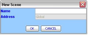
Once you select this menu you will be presented with the “New Scene” dialog (see Figure 12) requesting a name for the new Scene. Enter the name you prefer (the name can be changed at a later time) and click on “Ok”. The new scene will be added to the tree view on the left pane.
This operation performs the same action as the New Scene button on the tool bar ().
You can drag and drop any one of the devices already linked to the system into any scene. If you click and drag correctly you will see a plus sign next to the device you are dragging. Dragging devices to scenes will not remove it from the master list of devices (ISY Node) or from other scene(s) they already belong to. As such, each device may belong to many scenes.
You can select multiple devices by holding down CNTRL key and selecting the devices with the mouse pointer. Drag the selected devices and drop them into the scene folder. A prompt screen to set which device is the controller or responder will be presented. Select the device then click on the “Controller/Responder” button to set the device. This button toggles between responder and controller.
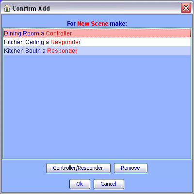
A device assigned as the controller of the scene is the device that initiates the scene. This device will control the responders according to the level and ramp rate settings.
It may take roughly 10 seconds to a few minutes to reprogram the device(s) to become part of a scene depending on the complexity and the number of other devices, and especially controllers/masters, for that scene.
This operation performs the same action as the New Scene button on the tool bar.
