ISY Users:V5:ZWave:Advanced User Guide One Page
Z-Wave Plus™ for ISY-994 series Advanced User Guide
This guide assumes the ISY has been successfully installed and that the Administrative Console is available. See Getting Started
This product can be operated in any Z-Wave™ network with other Z-Wave certified devices from other manufacturers. All non-battery operated nodes within the network will act as repeaters regardless of vendor to increase reliability of the network.
This product is a security enabled Z-Wave product that is able to use encrypted Z-Wave messages to communicate with other security enabled Z-Wave products.
The ISY supports S0 security, but does not support S2 security.
Admin Console
The Admin Console is the primary interface for creating, configuring, and monitoring your Z-Wave network.
Related
Node View
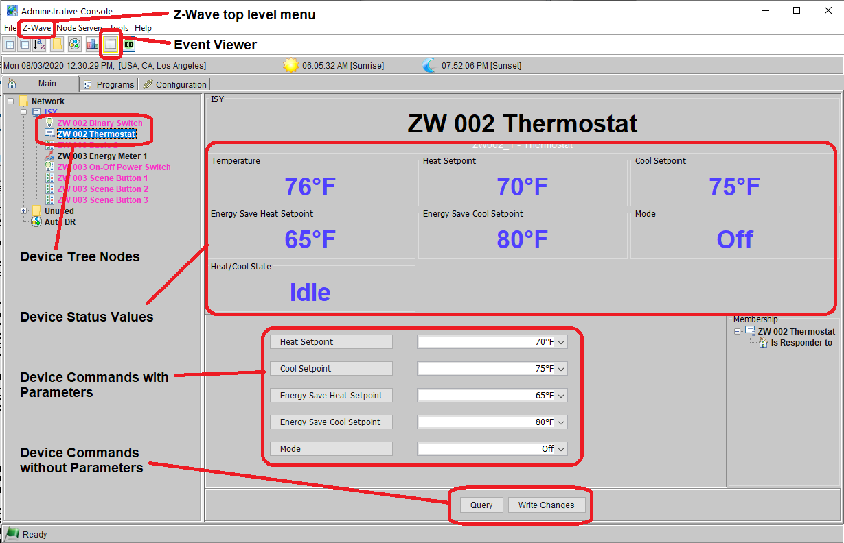
The Administrative Console (Admin Console) is the main GUI interface to the ISY. When a Z-Wave Device Tree Node is selected, the Device Status Values are shown in large font at the top of the page, and the Device Commands are shown at the bottom of the page. Some Z-Wave devices are represented as multiple device tree nodes. In this example, the thermostat also has a binary switch, which is represented in a different node.
Commands
Device commands may be issued from the device page in the Admin Console or from ISY programs. On the device page you will see a cycle button beside parameters that are optional. In programs you will see this as well, but in addition, you can specify an ISY variable as a parameter rather than a literal value.
The cycle button allows you to cycle through all the options for the parameter.
Top Level Menu & Buttons
Top Level Buttons
 /
/ 
- Expand or collapse the device tree

- Sort the devices in the device tree. Use this button to sort the devices in the tree, or to refresh the tree after adding a device.

- Create a new folder

- Create a new scene (group)

- Shows a chart of device activity

- Opens the event viewer. The event viewer shows ISY activity with detail increasing as the event viewer level increases.

- This button is not used by Z-Wave.
Z-Wave Top Level Menu
This menu will change depending on how the ISY is made part of the Z-Wave network. For example, Learn Mode is not available if the ISY is the SIS and the network is not empty. There is also a Controller Shift option that is only made available when there is no SIS in the Z-Wave network and the ISY is the Primary Controller.
Add a Z-Wave Device
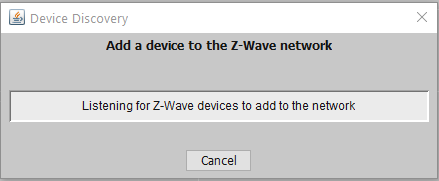
- Select Z-Wave | Add a Z-Wave Device and wait for a popup window to appear.
- If the popup window does not appear, Select Z-Wave | Advanced | Stop Adding or Removing a Z-Wave Device then try again.
- Put the Z-Wave device you are adding into learn Mode. Refer to the user guide for your product on how to do this. In many cases this just requires you to press a button on the device.
- The ISY will begin adding the device (this may occur a few seconds after you put the device into learn mode).
- The popup window will go away and you will see your device added to the tree.
Note: To add a device, it must not already be in a Z-Wave network. Therefore, if you are having trouble adding a device try removing it first.
Remove a Z-Wave Device
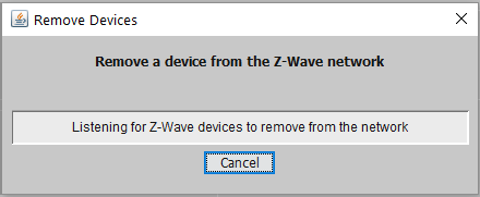
- Select Z-Wave | Remove a Z-Wave Device and wait for a popup window to appear.
- If the popup window does not appear, Select Z-Wave | Advanced | Stop Adding or Removing a Z-Wave Device then try again.
- Put the Z-Wave device into learn Mode. Refer to the user guide for your product on how to do this. In many cases this just requires you to press a button on the device.
- The ISY will remove the device (this may occur a few seconds after you put the device intolearn mode).
- The popup window will go away and the nodes for the device will be removed from the tree.
Learn Mode
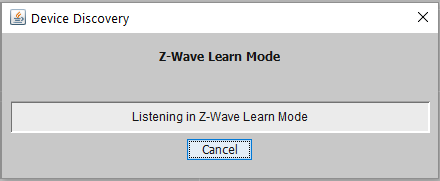
Learn Mode is used to Add the ISY to a Z-Wave Network, Remove the ISY from a Z-Wave Network, or update its information when already part of a Z-Wave network. When in Learn Mode, it is up to the other controller to determine which action is taken.
- Select Z-Wave | Learn Mode and wait for a popup window to appear.
- If the popup window does not appear, Select Z-Wave | Advanced | Stop Adding or Removing a Z-Wave Device then try again.
- The ISY will now wait to receive information from another Z-Wave device performing an action such as Add, Remove, etc.
- The popup window will go away when the operation is complete.
- In some cases this may take 30 to 60 seconds or longer to complete.
Note: Learn Mode is only available if the Z-Wave network is empty or the ISY is not the SIS for the Z-Wave network.
Synchronize Nodes
Synchronizes nodes and other information in the ISY for a Z-Wave device with the actual device information retrieved from the Z-Wave dongle and the device itself.
- New & Deleted
- Synchronizes devices that either do not exist in the ISY yet, or, exist in the ISY but no longer exist in the Z-Wave network.
- All
- Synchronizes all devices in the Z-Wave network
Options
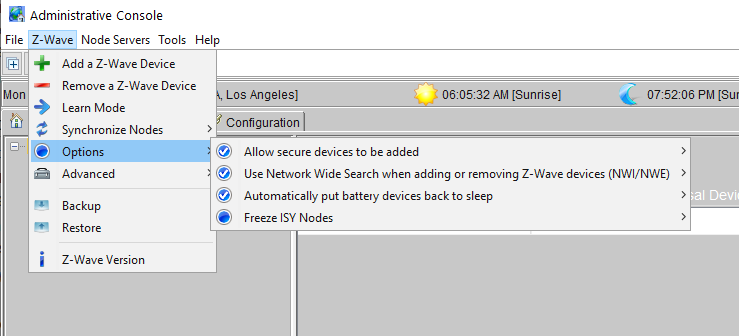
- Z-Wave | Options | Allow secure devices to be added allows the user to prevent devices from being added using S0 security.
- Z-Wave | Options | Use Network Wide Search when adding or removing Z-Wave devices (NWI/NWE) to enable or disable NWI/NWE when adding or removing devices.
- Z-Wave | Options | Automatically put battery devices back to sleep allows the user to keep battery devices awake when they would normally be put back to sleep.
- Z-Wave | Options | Freeze ISY Nodes allows the user to prevent the automatic creation of additional ISY Z-Wave nodes. This option is automatically turned off when adding a device.
Advanced | Stop Adding or Removing a Device
Stops any Add/Remove device command currently running in the Z-Wave dongle.
Advanced | Factory Reset Z-Wave dongle
Factory resets the Z-Wave dongle (not the entire ISY). When the Z-Wave dongle in the ISY is factory reset it is given a new Home Id and new S0 security keys are generated.
If this controller is the primary controller for your network, resetting it will result in the nodes in your network being orphaned and it will be necessary after the reset to exclude and re-include all of the nodes in the network. If this controller is being used as a secondary controller in the network, use this procedure to reset this controller only in the event that the network primary controller is missing or otherwise inoperable.
Advanced | Z-Wave Information
Provides some low-level Z-Wave network information generally regarding the ISY's participation in the Z-Wave network.
Backup
Backup the Z-Wave dongle into the Z-Wave dongle backup file in the ISY. Whenever you do a backup, the existing backup file is overwritten.
To back up the ISY and the Z-Wave dongle, you first backup the Z-Wave dongle, and then backup the ISY. The Z-Wave dongle backup file is stored as just another file inside the ISY backup zip file.
Restore
Restore the Z-Wave dongle using the Z-Wave dongle backup file in the ISY. When the ISY itself is restored, the Z-Wave dongle backup file is also restored from that backup.
Z-Wave Version
Shows the Z-Wave version and library being used by the Z-Wave dongle.
Node Menu
Query
This queries the device and may create nodes for the device if they failed to create when the device was added (because of communication problems for example).
For battery powered Z-Wave devices that are not Always Awake, the query will occur the next time the device wakes up.
Rename
Use this to rename the node
Disable
The node is essentially shut down and commands are not sent to it by the ISY.
Group Devices
Organizes all the nodes for the device or channel under the primary node for the device or channel.
Delete
Deletes the specific node, or all the nodes for the device or channel if this is the primary node for the device or channel.
Add to Scene ...
Add this node to an existing scene as either a controller or a responder
Move to Folder ...
Move this node to an existing folder
Write Updates to Device
Attempt to write any pending changes (such as associations) to the device regardless of whether it is awake or not.
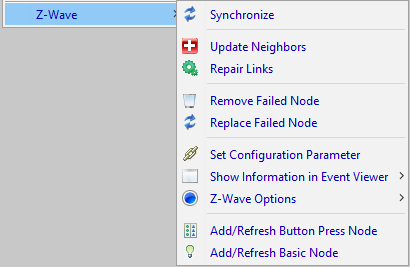
Z-Wave Submenu
This menu will change depending on the features of the device. For example, if it does not support the Basic command class there will be no option to create a Basic node.
This menu appears for Z-Wave nodes only.
Synchronize
Synchronizes the ISY nodes and the data associated with them with the actual data supplied by the device. In some cases this will cause ISY nodes to be deleted, created, and/or recreated.
Whenever a node is deleted it is first removed from all scenes. If the node is recreated, it is not put back into those scenes; this would have to be done manually by the user.
Update Neighbors
Updates the set of neighboring Z-Wave devices that this device can communicate with directly. This helps in routing messages throughout the Z-Wave network.
Repair Links
Rewrites all the associations and other related settings to the Z-Wave device
Remove Failed Node
If a Z-Wave device is no longer available for any reason then this command can be used to forcibly remove it from the Z-Wave network. The device will not be removed if it still responds to messages sent to it.
Replace Failed Node
If a Z-Wave device is no longer available for any reason then this command can be used to forcibly replace it from the Z-Wave network. The device will not be replaced if it still responds to messages sent to it.
Set Configuration Parameter
Query and set a Z-Wave configuration parameters for this device. This is a little more of a free form way of setting these values rather than using the command as it appears in the device screen.
Show Information in Event Viewer
These commands write information about a Z-Wave device to the Event Viewer
- All
- Shows Node Details, Link Details and Network Details in the event viewer.
- Node Details
- Show device type information, command classes + versions, and whether the device was included securely or not
- Link Details
- Shows the associations for this device
- Network Details
- Shows neighboring devices
Z-Wave Options
Always Awake
Indicates whether this device is always awake. Some battery powered devices can be essentially mains powered and thus can remain awake.
Automatically sends status updates
Indicates whether or not the device automatically sends updates when status changes. For example, if a lamp is turned off does it automatically send the status to the ISY, or, does the ISY have to query the device.
This option is useful for performance and/or reducing Z-Wave communication traffic.
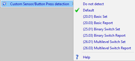
Custom Sensor/Button Press detection
This option appears for Basic Controller, Binary Switch, Multilevel Switch, and Custom Button Press nodes.
Whenever a sensor has been triggered or a button has been pressed, the Z-Wave device may send out a message to the ISY as well as other Z-Wave devices.
This option tells the ISY what message to look for when this happens.
For most devices, the ISY can figure this out itself, but for others you will need to set this option to a custom value. Opening the Event Viewer to level 3 and looking at the Z-Wave messages generated will indicate what message is sent when the button is pressed or sensor is triggered.
- Do Not Detect
- Instructs the ISY to not attempt to detect a button press. This can be useful for performance and/or reducing Z-Wave communication traffic.
- Default
- The ISY will attempt to detect the button press based on characteristics of the device such as device type, command classes supported, etc.
- (20.01) Basic Set
- Any Basic Set message will indicate a button press. If the value is zero, it will generate an Off event, otherwise it will generate an On event.
- (20.03) Basic Report
- Any Basic Report message that is not the result of a query will indicate a button press. If the value is zero, it will generate an Off event, otherwise it will generate an On event.
- (25.01) Binary Switch Set
- Any Binary Switch Set message will indicate a button press. If the value is zero, it will generate an Off event, otherwise it will generate an On event.
- (25.03) Binary Switch Report
- Any Binary Switch Report message that is not the result of a query will indicate a button press. If the value is zero, it will generate an Off event, otherwise it will generate an On event.
- (26.01) Multilevel Switch Set
- Any Multilevel Switch Set message will indicate a button press. If the value is zero, it will generate an Off event, otherwise it will generate an On event.
- (26.03) Multilevel Switch Report
- Any Multilevel Switch Report message that is not the result of a query will indicate a button press. If the value is zero, it will generate an Off event, otherwise it will generate an On event.
User Code Report Style
This option appears for devices that support user codes (such as door locks).
Z-Wave devices that support user codes report the actual user number in different ways. In most cases the Default setting is sufficient but in cases where it is not, try one of the other options until you see the ISY correctly detect the user number. For example, open a door lock with a user code and if you do not see the correct user code then try a different setting.
Add/Refresh Button Press Node
Create a node that detects when a button is pressed, a sensor is triggered, or just generally when a specific message is sent from the device. Once created, change the Custom Sensor/Button Press Detection Z-Wave Option for this node to the message you want to detect.
This node can be used as a scene controller as well as in programs.
Add/Refresh Basic Node
This option creates a Basic Node for the device.
You may want to create a Basic Node if the device supports a custom mapping or set of values (normally provided in the description of the device). For most devices the is not needed.
If you do not see this entry the menu then the device does not support the Basic command class.
Scenes
Groups & Scenes
The terminology for scene has dual meanings in ISY for historical reasons. In some cases it describes the group (scene) object that contains a set of controller and responder nodes, and in others it describes a single controller (and its links to responders) within the group.
- Controller
- A node such as a light switch that can control responders (e.g. can turn something on/off)
- In some cases, a controller may also be a responder.
- Responder
- A node such as a lamp that can be controlled by a controller (e.g. can be turned on/off)
- Group
- Often referred to as a scene, a group is an object containing a collection of controllers and responders. It may contain many controllers and many responders.
- Scene
- A single controller linked to one or more responders.
ISY scenes define how controllers control and communicate with responders in the scene. The ISY group itself acts as a controller and therefore also has links to all of the responders in the scene.
Creating a Scene
Create a scene by pressing the ![]() button in the row of top level buttons.
After giving the scene a name and pressing the Ok button the new scene will appear in the device tree.
button in the row of top level buttons.
After giving the scene a name and pressing the Ok button the new scene will appear in the device tree.
Removing a Scene
To remove a scene, right+click on the scene in the device tree and select Delete Scene. A popup will appear asking to confirm the deletion of the scene. Prior to deleting the scene all scene members are removed from the scene.
Adding a Controller to a Scene
To add a node as a controller to a scene, right+click on the Z-Wave controller node and select Add to Scene ... In the first popup menu, choose the scene you just created. In the second popup menu, make sure to add it to the scene as a Controller
Adding a Responder to a Scene
To add a node as a responder to a scene, right+click on the Z-Wave responder node and select Add to Scene ... In the first popup menu, choose the scene you just created. In the second popup menu, make sure to add it to the scene as a Responder
Removing a Controller or Responder from a Scene
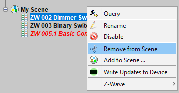
Locate the controller or responder in the device tree under the Group and then right+click on it to get the popup menu. Select Remove from Scene to remove it from the scene (group).
Any associations or other information related to the links will be removed from the node being removed.
Scene Link Types
There are four different ways a controller can control a responder in a scene.
- Native (Controller→Responder)
- For Z-Wave nodes, this is an Association between a Z-Wave controller (such as a switch or a sensor), and a compatible Z-Wave responder (such as a lamp, valve, door lock, etc.).
- In addition to associations, devices that support Z-Wave scenes are controlled using the Scene Activation, Scene Actuator, and Scene Controller Configuration command classes.
- Default (Controller→ISY→Responder)
- Whatever command (On,Off,etc.) that is sent by the controller is forwarded to the responder by the ISY.
- The ISY must be able to detect the button press or sensor triggering for this action to take place.
- Command (Controller→ISY→Responder)
- Same as Default except when the controller sends an On command the ISY sends the command specified in the link to the responder.
- (Controller→ISY→Responder)
- Ignore
- No link is made between the controller and responder.
Association between Controller and responder
Select the controller node in the device tree under the Group (scene) and you will see a table containing all the responders and the controller itself.
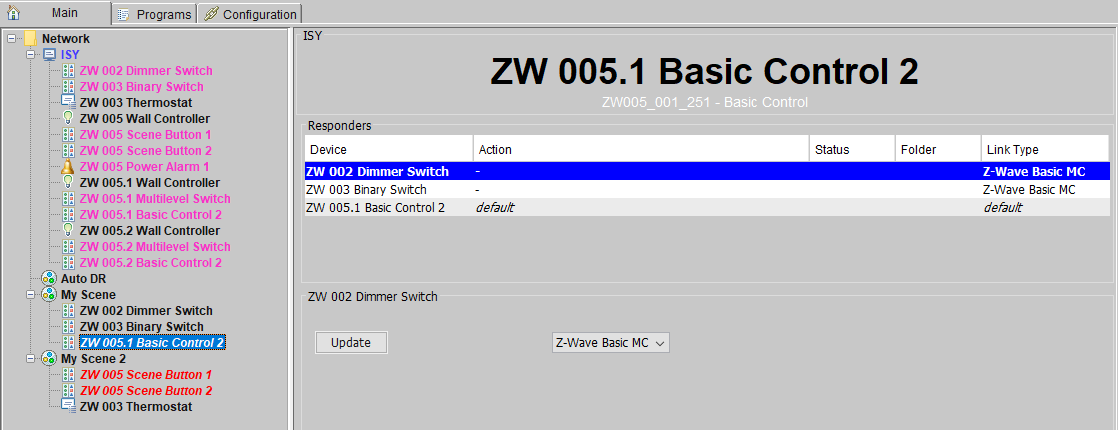
Select a responder in the table to modify the link between the controller and the responder. The above example for My Scene shows two responders ZW 002 Dimmer Switch and ZW 003 Binary Switch, each of which are associated with the controller ZW 005.1 Basic Control 2. The association is compatible because the controller sends out Basic Set and the responders support the Basic command class.
A link can be changed by selecting a different link type in the combobox and the pressing the Update button.
Indirect control between a controller and responder
Select the controller node in the device tree under the Group (scene) and you will see a table containing all the responders and the controller itself.
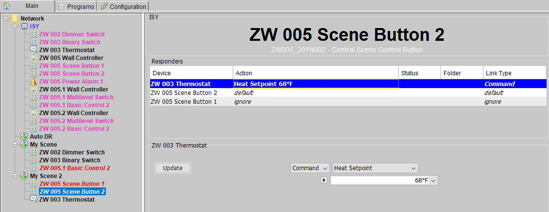
In this example there are two controllers and one responder in My Scene 2. ZW 005 Scene Button 2 sets the Heat Setpoint of thermostat ZW 003 Thermostat to 68F. No association between the controller and responder is made because we are using the nodes for Central Scene Controller buttons. Instead, the ISY is associated with the controller, detects the button press, and then the ISY issues the setpoint command to the thermostat.
An ISY program variable can be used as a command parameter in the command link. In this example, $Int_1 is used instead of a literal value like 68F. Whenever the scene is activated, the current value of the $Int_1 is used for the setpoint value.
Press the cycle button ![]() to alternate between using a literal value and an ISY program variable.
to alternate between using a literal value and an ISY program variable.
Indirect control of a scene is only works if the ISY can detect a button has been pressed or a sensor has been triggered etc..
Program Variables
Program Variables Tab
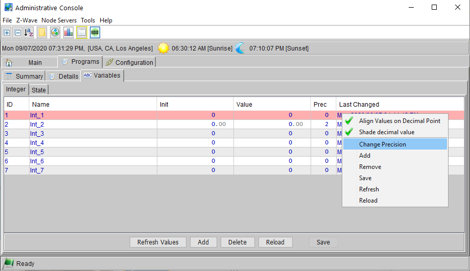
- The definitions for all the variables are under the Variables tab in Programs.
- All variables are stored as 4 byte signed integers with an implied decimal point defined by a precision (the number of implied decimal points). When a variable is created it is given a precision of 0.
- When you add/remove/rename or change the precision of a variable you must save your changes before they will take effect.
- When you modify either the init value or the current value the change takes place immediately and you do not have to hit save.
- The timestamp column shows the last time the current value of the variable was changed.
Integer Variables
- A signed integer (32 bit)
- Arithmetic operations available in Actions
- Comparison operations available in conditions
- Initialized at startup
- Changes to the value do not cause an event to be sent
State Variables
- Identical to an Integer variable except that changes to the value do cause an event to be sent, causing programs to run
In Programs
- For both actions and conditions, variables are shown with just their name prefixed by $.
- For example, if you define a variable named counter it will show up as $counter in your programs.
Initialization
- At start-up, all variables are initialized to their predefined init value, or zero, if no init value has been specified. The init value may be set by editing the init value in the table containing the variable definitions.
- The init value may also be set in programs, thus providing a means of persisting values across restarts.
x : A variable a : Either a variable or an integer constant
Initialize $x Init To a
This sets the init value for this variable, it does not modify the current value of the variable.
You may of course set the init value to the current value of the variable by doing this:
$x Init To $x
Persistence
It may be desirable to maintain the value of some variables across restarts of the ISY. This must be done explicitly by changing the init value of the variable (as described above).
One of the reasons we don't automatically persist all of the variables is that the value of a variable would have to written to persistent storage (a file on the SD Card) each time it changes.
Operators
All operations are in the form $variable op <value or variable>.
Calculations
Most operations do both a calculation and assignment, for example:
$counter += 1
is equivalent to the more familiar
$counter = $counter + 1
x : A variable
a : Either a variable or an integer constant
Assign        $x  = a
Add           $x += a
Subract       $x -= a
Multiply      $x *= a
Divide        $x /= a
Remainder     $x %= a
And (binary)  $x &= a
Or (binary)   $x |= a
Xor (binary)  $x ^= a
Functions
Random
$x = Random a (Assigns $x a random value between 1..a inclusive, or 1 if a <= 1)
$x = Random 3      // Assigns $x either 1, 2, or 3
$y = 500
$x = Random $y     // Assigns $x a random value between 1 and the value of $y (e.g. 1..500)
$x = Random -50    // Assigns $x a value of 1
Comparison
Equal                  $x is a
Not Equal              $x is not a
Less Than              $x < a
Less Than or Equal     $x <= a
Greater Than           $x > a
Greater Than or Equal  $x >= a
Example
A loop that could be used to implement an off timer that increases in 5-minutes intervals. For example, another program could be written to increase $BathRoomLightCount by 1 each time an On button is pressed.
$BathRoomLightCount is an Integer Variable
If
       $BathRoomLightCount > 0
Then
       Wait  5 minutes
       $BathRoomLightCount -= 1
       Run Program 'Bathroom Timer' (If)
Else
  - No Actions - (To add one, press 'Action')

